Skip to content
Submit
Close search
Home
Build Your Flow Meter
Liquid Flow Meters
expand
collapse
Liquid Flow Meters
Coriolis Flow Meter 3/8" to 10"
Magnetic Flow Meter 1/2" to 96"
Vortex Flow Meter 1/2" to 72"
Clamp On Ultrasonic Flow Meter 1" to 48"
Inline Ultrasonic Flow Meter 1/2" to 6"
Turbine Flow Meter 1/2" to 8"
Gas Flow Meters
expand
collapse
Gas Flow Meters
Coriolis Flow Meter 3/8" to 10"
Vortex Flow Meter 1/2" to 72"
Industrial Thermal Mass Flow Meter 1/2" to 8"
MEMS Thermal Mass Flow Meter 1/2" to 2"
100 SLPM Flow Meter
Low Flow Gas Mass Flow Meter
Thermal Mass Flow Meter/Controller 1" to 2"
Specialty Flow Meters
expand
collapse
Specialty Flow Meters
Asphalt Flow Meter
Boiler Flow Meter
BTU Meter
Compressed Air Flow Meter
Flare Gas Flow Meter
Methane Flow Meter
Natural Gas Flow Meter
Oil Flow Meter
Sanitary Flow Meter
Slurry Flow Meter
Steam Flow Meter
Wastewater Flow Meter
Coriolis Flow Meters
expand
collapse
Coriolis Flow Meters
Coriolis Flow Meter 3/8" to 10"
Magnetic Flow Meters
expand
collapse
Magnetic Flow Meters
Magnetic Flow Meter 1/2" to 96"
Grounding Ring 1" to 12"
Vortex Flow Meters
expand
collapse
Vortex Flow Meters
Vortex Flow Meter 1/2" to 72"
Ultrasonic Flow Meters
expand
collapse
Ultrasonic Flow Meters
Clamp On Ultrasonic Flow Meter 1" to 48"
Inline Ultrasonic Flow Meter 1/2" to 6"
Thermal Mass Flow Meters
expand
collapse
Thermal Mass Flow Meters
Industrial Thermal Mass Flow Meter 1/2" to 8"
MEMS Thermal Mass Flow Meter 1/2" to 2"
Thermal Mass Flow Meter/Controller 1" to 2"
Turbine Flow Meters
expand
collapse
Turbine Flow Meters
Turbine Flow Meter 1/2" to 8"
Control Valves
expand
collapse
Control Valves
2" NPT Modulating Control Ball Valve
4" ANSI Modulating Ball Valve
6" ANSI Modulating Ball Valve
Industrial Automation
expand
collapse
Industrial Automation
Totalogger™ HMI Data Logging System
TotalControl™ MFC Control Box
Cloud Data Logger
Modbus Simple Software
Calibration Services
expand
collapse
Calibration Services
Gas Loop Calibration
Water Loop Calibration
Gravimetric Prover Calibration
Piston Prover Calibration
Downloads
expand
collapse
Downloads
Configuration Software
Android App
How the Thermal Mass Flow Meter Works
Thermal Mass Flow Meter Wiring Diagrams
Thermal Mass Flow Meter User Video Instructions
Natural Gas Flow Meter BTU to SCFH
How To Calibrate a MAG meter or any Liquid Flow Meter
ModBus and Serial Terminal Instructions
Helpful Links
About Us
expand
collapse
About Us
Our Story
Blog
Contact Us
expand
collapse
Contact Us
Contact Us
Wire Transfer - Credit App -Payments
Terms & Conditions
USE CODE "FREESHIP" FOR FREE GROUND SHIPPING ON ONLINE DOMESTIC ORDERS
Tactical Flow Meter | Coriolis Flow Meters, Electromagnetic MAG Flow Meters, Thermal Flow Meters, Ultrasonic Flow Meters, Vortex Flow Meters, Control Valves, Industrial Automation, Calibration Services
Home
Build Your Flow Meter
Liquid Flow Meters
expand
Coriolis Flow Meter 3/8" to 10"
Magnetic Flow Meter 1/2" to 96"
Vortex Flow Meter 1/2" to 72"
Clamp On Ultrasonic Flow Meter 1" to 48"
Inline Ultrasonic Flow Meter 1/2" to 6"
Turbine Flow Meter 1/2" to 8"
Gas Flow Meters
expand
Coriolis Flow Meter 3/8" to 10"
Vortex Flow Meter 1/2" to 72"
Industrial Thermal Mass Flow Meter 1/2" to 8"
MEMS Thermal Mass Flow Meter 1/2" to 2"
100 SLPM Flow Meter
Low Flow Gas Mass Flow Meter
Thermal Mass Flow Meter/Controller 1" to 2"
Specialty Flow Meters
expand
Asphalt Flow Meter
Boiler Flow Meter
BTU Meter
Compressed Air Flow Meter
Flare Gas Flow Meter
Methane Flow Meter
Natural Gas Flow Meter
Oil Flow Meter
Sanitary Flow Meter
Slurry Flow Meter
Steam Flow Meter
Wastewater Flow Meter
Coriolis Flow Meters
expand
Coriolis Flow Meter 3/8" to 10"
Magnetic Flow Meters
expand
Magnetic Flow Meter 1/2" to 96"
Grounding Ring 1" to 12"
Vortex Flow Meters
expand
Vortex Flow Meter 1/2" to 72"
Ultrasonic Flow Meters
expand
Clamp On Ultrasonic Flow Meter 1" to 48"
Inline Ultrasonic Flow Meter 1/2" to 6"
Thermal Mass Flow Meters
expand
Industrial Thermal Mass Flow Meter 1/2" to 8"
MEMS Thermal Mass Flow Meter 1/2" to 2"
Thermal Mass Flow Meter/Controller 1" to 2"
Turbine Flow Meters
expand
Turbine Flow Meter 1/2" to 8"
Control Valves
expand
2" NPT Modulating Control Ball Valve
4" ANSI Modulating Ball Valve
6" ANSI Modulating Ball Valve
Industrial Automation
expand
Totalogger™ HMI Data Logging System
TotalControl™ MFC Control Box
Cloud Data Logger
Modbus Simple Software
Calibration Services
expand
Gas Loop Calibration
Water Loop Calibration
Gravimetric Prover Calibration
Piston Prover Calibration
Downloads
expand
Configuration Software
Android App
How the Thermal Mass Flow Meter Works
Thermal Mass Flow Meter Wiring Diagrams
Thermal Mass Flow Meter User Video Instructions
Natural Gas Flow Meter BTU to SCFH
How To Calibrate a MAG meter or any Liquid Flow Meter
ModBus and Serial Terminal Instructions
Helpful Links
About Us
expand
Our Story
Blog
Contact Us
expand
Contact Us
Wire Transfer - Credit App -Payments
Terms & Conditions
Submit
Search
Shopping Cart
Shopping Cart
expand/collapse
Home of the Big-4™️
Coriolis, MAG, Vortex, and Thermal Flow Meters
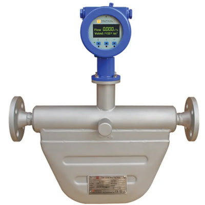
Coriolis Mass Flow Meter
for Liquid Flow and Gas Flow
3/8" to 10" UL APPROVED 0.1% Accuracy
$5,900.00
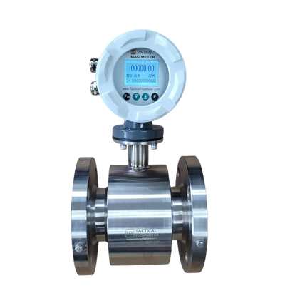
Magnetic Flow Meter
for Liquid Flow
1/2" to 96"
$1,500.00
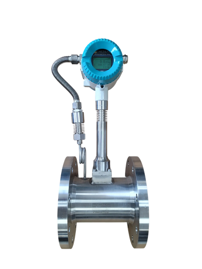
Multivariable Vortex Flow Meter
for Liquid Flow and Gas Flow
1/2" to 72"
$2,600.00
Thermal Mass Flow Meter
for Industrial Gas Flow
1/2" to 8"
$2,240.00
Thermal Mass Flow Meter
for Gas Flow (Methane and Natural Gas)
1/2" to 2" NPT
$1,400.00
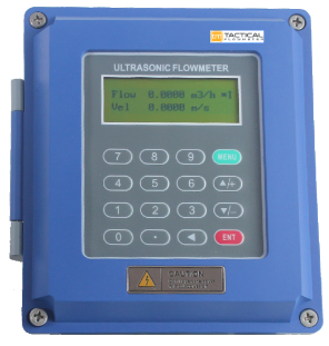
Clamp On Ultrasonic Flow Meter
for Liquid Flow
1" to 48"
+/- 1.0%
$2,200.00
Clamp On Ultrasonic Flow Meter
for Liquid Flow
0.6" to 228"
+/- 1.0%
$1,900.00
Inline Ultrasonic Flow Meter
for Liquid Flow
1/2" to 6"
$2,000.00
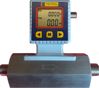
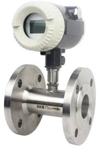
Turbine Flow Meter
for Liquid Flow
1/2" to 8"
$925.00
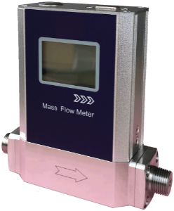
15 SLPM to 100 SLPM Low Flow Tactical Flow Meter, Battery Powered for 2 years
$2,215.00
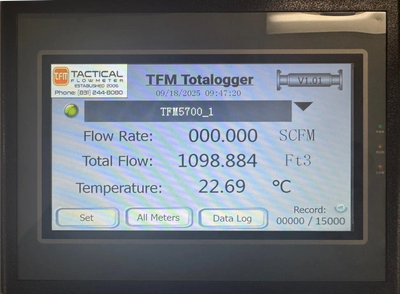
Totalogger™
HMI Data Logging System
Regular price
$2,500.00
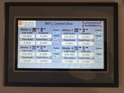
TotalControl™
MFC Control Box
Regular price
$2,000.00
Cloud Data Logger System
Regular price
$365.00
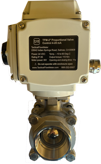
2" NPT Modulating Control Ball Valve
Regular price
$1,400.00
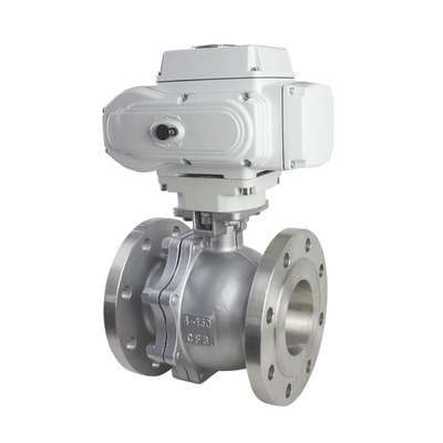
4" ANSI Modulating Control Ball Valve
Regular price
$3,000.00
View all