
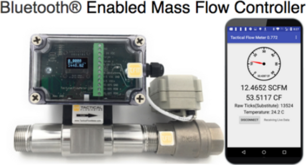


1" Thermal Mass Flow Controller
for Gas Flow
Regular price
$4,195.00
Our thermal Mass Flow Meter or Controller is capable of providing direct measurement of mass flow, as opposed to most other methods that measure volumetric flow & require separate measurements for temperature & pressure in order to calculate density &, ultimately, the mass flow.
We also sell gas Mass flow Controllers built to measure air & gas. These flow meters shipping from stock (usually within 48hrs) & are configured for you.
Our EASY to use gas Mass Flow Controllers are in stock at prices that beat our competition.
1" NPT 0-20 SCFM AND TEMPERATURE
- Accuracy: +/- 1% of reading plus +/-0.5% of full scale
- Flow Control adjustable via digital communications, on board encoder, or SmartPhone.
- Repeatability of +/- 0.2% of full scale
- 1” MNPT Pipe size Inlet/ 1" FNPT pipe size outlet
- Flow control range to 0-20 SCFM
- OLED Display
- Measures any inert gas and any non-condensing clean gas
- Flammable gases: methane, propane, digester gas, natural gas
- 100:1 turndown
- Temperature:
- Gas: -40°F (-40°C) to 350°F (200°C)
- Ambient: -40° F to 120° F (-40° C to 50° C)
- Pressure, 25 PSIG Max
- Adjustable Response time from .1 to 6 seconds to achieve 63% of final value
- Power Requirement 18 to 30 VDC (regulated), 125 mA maximum;
- Nylon 6/6, 6061T6 Aluminum or 316 stainless-steel construction
- Output signals: Modbus RTU, USB-RS-232, 4–20 mA , 0–5 VDC, and Pulse User definable pulse or frequency for totalized or flow rate indication
- Digital communications solutions include: Modbus RTU, USB, Bluetooth
- IP66 Enclosure
Mass Flow Meters and Controllers Re-imagined
Main User Program Index
Click here to view the Complete User Instructions.
Click here to view how to connect to Bluetooth.
Click here to view for MORE Bluetooth tips.
Click here to view how to Validate Your Flow Meter.
Click here to view how to use the Datalog.
Click here to learn how to read the OLED Local Display.
Click here to show QR Code so you can view this site on your SmartPhone.
Click here to view How to use the 0-5VDC and 4-20mA Outputs, basic overview.
Click here to view Details on adjusting 0-5VDC and 4-20mA Outputs.
For Wiring Diagrams and connections Click here
Click here to use the Terminal and ModBus and RealTime graph.
Click here for detailed ModBus instructions
Click here to work with the Totalizer and Pulse Counter, basic overview.
Click here to Set Up your Totalizer and Pulse Counter with some examples.
Click here to view how to use Setup tab for enabling writing.
Click here to use the Configuration tab to view the meter variables.
Click here to work with the Totalizer and configure the pulse counter.
Click here to work with the Calibration Screen for editing the calibration variables.
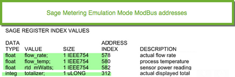
The table below shows the Register addresses that are in place to support the use the same register scheme used in any Sage Metering ModBus equipped Thermal Mass Flow Meter. The Sage Metering product indicates the raw flow reading in mW, typically in the range of 40 mW to 900 mW. As such, we scale the output of the Tactical Flow meter's 0-32767 Raw Ticks output to the range of 40 to 900 mW when using the ModBus command 582. This provides for easy comparison of the raw values.
Click here to go back to the Index.


Click here to go back to the Index.
The QR Code is VERY HANDY to read with your Smart Phone so you can have these instructions on your portable device when you go to the flow meter in the field. These videos render very fast on all Smart Phones.
Click here to go back to the Index.
We demonstrate the operation of the User Program with a Windows Machine to allow you to understand the basic principles of the mass flow meter/controller. We demonstrate the operation of the User Program with a Windows Machine to allow you to understand the basic principles of the mass flow meter/controller. This video show all aspects of the program and is available in each category from the index values shown above.
Click here to go back to the Index.
We demonstrate the method of setting up the mass flow meter/controller with a Windows Machine with Bluetooth using the User Program.
The Pairing Code is 1234 on all the flow meters.
Click here to go back to the Index.
We demonstrate more methods for using the PC and Bluetooth and how to discover which Bluetooth device is connected to your Flow Meter.
Click here to go back to the Index.
We demonstrate the method of validating the calibration of the mass flow meter/controller with a Windows Machine with the User Program.
Click here to go back to the Index.
We demonstrate the method of downloading/viewing and plotting the datalog data from the mass flow meter/controller with a Windows Machine with the User Program.
Click here to go back to the Index.
This video shows how the 4-20 and 0-5 VDC Outputs can be validated manually.
Click here to go back to the Index.
This video shows examples of adjusting the 4-20 and 0-5 VDC outputs to correlate with the attached data acquisition system.
Click here to go back to the Index.
We demonstrate the method of setting up the mass flow meter/controller with a Windows Machine with Bluetooth using the User Program.
Click here to go back to the Index.
We demonstrate the method of validating the calibration of the mass flow meter/controller on a Windows Machine with the User Program.
Click here to go back to the Index.
We demonstrate the method of downloading/viewing and plotting the datalog data from the mass flow meter/controller with a Windows Machine with the User Program.
Click here to go back to the Index.
We demonstrate the method of validating the calibration of the mass flow meter/controller with a Windows Machine with the User Program.
Click here to go back to the Index.
We demonstrate the method of using the Terminal and the ModBus functions for the mass flow meter/controller with a Windows Machine with the User Program.
Click here to go back to the Index.
We demonstrate the method of accessing the totalizer and pulse output of the mass flow meter/controller for a Windows Machine with the User Program.
Click here to go back to the Index.
We demonstrate the method of setting up your Pulse Counter to count at the rate that is supported by your connected pulse counter. We show the part that accomplishes the pulse counting as well as the specification sheet for an Omron H7EC as an example.
Click here to go back to the Index.
We demonstrate the setup screen of the mass flow meter/controller for a Windows Machine with the User Program.
Click here to go back to the Index.
We demonstrate the method of accessing the configuration of the mass flow meter/controller for a Windows Machine with the User Program.
Click here to go back to the Index.
We demonstrate the method of accessing the calibration features of the mass flow meter/controller for a Windows Machine with the User Program.