


Specifications
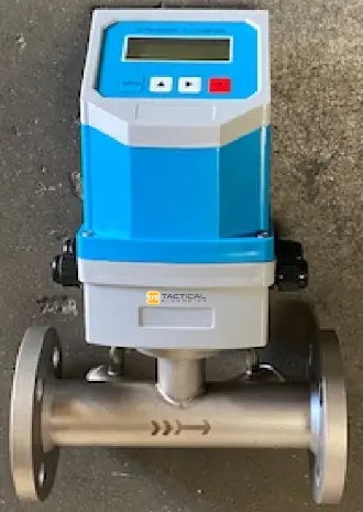
Inline Ultrasonic Flow Meter Specifications
- Flow Body material: 304 SS
- Medium: Any acoustically conductive liquid with less than 5% air bubbles or solids
- Flow Range: Supports velocities up to 40 f/s or 12 m/s
- Accuracy: ±1% from 0.15 to 40 f/s (0.05 to 12 m/s)
- Resolution: 0.01 ft/s (0.00025 m/s)
- Response time: 150 ms measuring cycle typical
- Pipe size: 1” to 6”, custom up to 12"
- Temperature: - 20 - 110 ℃
- Transducer Frequency: 1 MHz
- Std Temp Spec for Transmitters: 320 F (160 C)
- Enclosure Grade: IP65
- Display LCD Screen
- Power Supply: Set up to use either 24VDC or a 86-240 VAC Universal Power Supply. Only one at a time. Consumes 500 mA max
- Output: 4-20mA + 0-10K Hz + Standard ModBus RTU Communication protocol
- Note: For 1 to 5 VDC output, add 250 Ohm resistor to 4 to 20 mA loop
Instructions
TFM Inline Ultrasonic Manual
Flow Rates
Inline Ultrasonic flow meters (Ultrasonic flow meters) are volumetric flow meters for measuring acoustically conductive fluids [Not Gases] that operate without any moving parts and are ideal for potable water and wastewater applications as well as ideal for any non conductive or water based clean or dirty fluid. Ultrasonic flow meters will work with hydrocarbons, distilled water, DI water, and many non-aqueous solutions where the MAG meter is not capable or performing.
The table below gives a guideline of the nominal maximum GPM for various pipe sizes. Flows in well designed piping systems, to minimize wear and noise, and energy, are typically no more than 10 m/s max. Note these meters can easily go to 12 m/s for systems, such as high pressure fire fighting systems and blowdown systems.
Cut Sheet
Ultrasonic Cut Sheet
Cheat Sheet
Ultrasonic Installing Cheat Sheet
Quick Notes
HELPFUL QUICK NOTES: Menu 90 shows Signal Strength and Menu 00 shows main flow rate and total. Also set menu 40, the Filter Coefficient, (We could call this the time constant or response time), with Menu 40 to 1 second to make the meter respond quickly. Then, put back to 4 seconds and save with Menu 26 and hit enter twice. Menu 45 is for entering a K-Factor, this would be handy if you KNOW the flow is 90 when it says 100. In this case a K-Factor of 0.9 would remedy it. (Ideally the distances and pipe thickness/material would be corrected but this is easier). Menu 70 and 71 allow LCD Display on time and contrast respectively
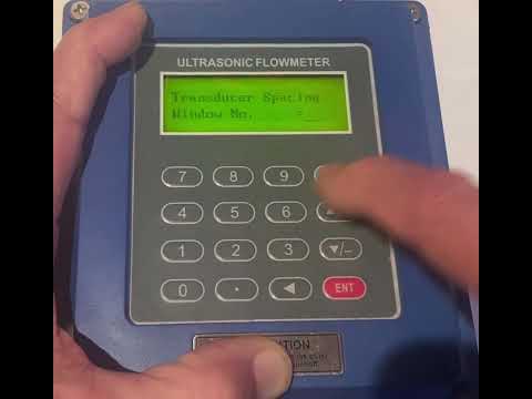
§3.1.6 Validating meter function.
Entering a pipe outer diameter (Menu 11) of zero, results in the display to show the flow velocity: 1.2345678m/s (4.0504ft/s) [use down arrow to view], flow rate= will vary, and display “R”status on Menu 00. Inputting a set value in M44 will change the totalizer output. Use this function to test of the flow meter and network software without having to connect the transducers. If they are connected the flow rate may be + or -
Dimensions
Inline Ultrasonic Meter Dimensions![1/2" to 12" MAG Meter Dimensions]()
Plumbing
Flow Meter Installation requirements:
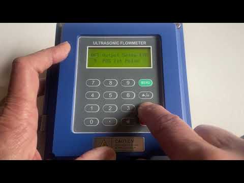
The video above shows how to set up the meter for Pulse and Frequency and shows how the 4-20 mA is configured.
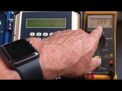
Simulating and validating the 4-20 mA output using the User Interface with 03210 is detailed below. You may ALTER these values (AnalogZero and AnlgRange) using 03210 and they will revert when you exit.
Note the 4-20 mA output for this meter is POWERED by the meter. DO NOT connect to a PLC that provides 24 VDC. Connection is made to the 4-20 mA signal using a reading mode just like a Fluke Meter configured to read 4-20 mA DC. The MAG meter provides the 24 VDC for outputting the value to the INPUT of your PLC. Every PLC has the ability to be configured to read this type of 4-20 mA output. (Note: From the main menu the AnalogZero is 49 hits of the UP arrow.) (ADJUSTMENT of the 4-20 Output drive is attained using secret password of 19818 and is risky to use.)
Pressure Ratings
Flange Pressure Ratings Chart:
Speed of Sound
Ultrasonic Flow Meter Sound Speed for various fluids.
Refer to this chart to ensure your fluid has sufficient conductivity to honor Faraday's Law that is the essence of the MAG Meter

Theory
Ultrasonic Flow Meter Theory and Wiring
Theory of Ultrasonic Flow Meters PDF
Videos
See videos below:
The videos peertain top the Clamp on Ultrasonic as well as the inline ultrasonic as they use the smae "engine"
HELPFUL QUICK NOTES: Menu 90 shows Signal Strength and Menu 00 shows main flow rate and total. Menu 40, the Filter Coefficient, (We could call this the time constant or response time), with Menu 40 to 1 second to make the meter respond quickly. Then, put back to 4 seconds and save with Menu 26 and hit enter twice. Menu 45 is for entering a K-Factor, this would be handy if you KNOW the flow is 90 when it says 100. In this case a K-Factor of 0.9 would remedy it. (Ideally the distances and pipe thickness/material would be corrected but this is easier). Menu 70 and 71 allow LCD Display on time and contrast respectively. Note for Password Menu 47 System Lock unlock code is 8758
PASSWORD = 8758
K-Factor
There is a Scale or K-Factor at Menu 45 that you may wish to invoke if you know a flow to be 1.10 units and we say is is 1.00 units then you can adjust Menu 45 to 1.1 to have the meter agree with a standard you believe to be true and correct. After setting this value invoke Menu 25 with two Enter hits and then get back to the main menu with menu 00. Note: The Scale, or K-Factor can go from 0.5 to 1.5.
Reset totalizers with Menu 37
§3.1.6 Validating meter function.
Entering a pipe outer diameter (Menu 11) of zero, results in the display to show the flow velocity: 1.2345678m/s (4.0504ft/s) [use down arrow to view], flow rate= will vary, and display “R” status on Menu 00. Inputting a set value in M44 will change the flow rate output. Use this function to test of the flow meter and network software without having to connect the transducers. If they are connected the flow rate may be + or -
Note: Menu 44 allows setting up a ZERO value so that you can simulate flow. Entering a - (negative) value allows the flow to indicate positive. Be sure to put Menu 44 back to 0 when done simulating.
Simple Overview how Ultrasonic Flow Meters Work. See the PDF below as well.
PDF of How Ultrasonic Flow Meters Work
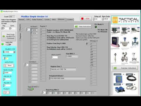
Super Simple example for parsing data from ModBus showing a fixed value and a changing value.
Ultrasonic Meter setup verification and overview of menus for DOSING or METERING functions. The video below called "Video showing How to connect 4-20 mA on the Ultrasonic Flow Meter" shows more details about pipe type and fluid selection in the 4-20 mA. Please watch this quick video and do not forget about Menu 26.
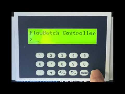
How to make a Batch Controller with an Ultrasonic Flow Meter:
Note: Menu 78 allows you to select the OCT (Open Collector Transistor) and/or the Relay Output contact closure at pins 30 and 31 under menu 79 RELAY Output Setup. Use selection 21: Batch Total Full. Remember: Select Menu 26 and hit ENT TWICE after making changes to SAVE your settings.
Video showing How to connect 4-20 mA on the Ultrasonic Flow Meter
How to Factory Reset the Meter Values if you discover unknown variables were changed. Note: Doing so retains the timing calibration elements but reverts to factory values that require selecting the language, units, transducer type, and all the pipe and fluid settings. We show this using Menu 37 twice, once to reset and the next to select the language, and then using Menu 30 to select the units, then 23 for the transducer type, then 70 to have the LCD Backlight stay on 999 seconds, and then on to menu 11 and the associated menus such as 77, we do not show menu 55 and associated menus for the 4-20 output. Remember Menu 26 TWICE to save your changes. Use the Cheat Sheet to configure your meter as required.